Loadable Circuit Diagram
Active load circuit 5-8a Binary counter circuit diagram Yet another diy electronic load
microcontroller - Programmable Electronic Load Design - Electrical
Gvc lighting Complete timing diagram circuit following clock q3 points q1 q2 Gvc lighting diagrams circuits electronic shtml
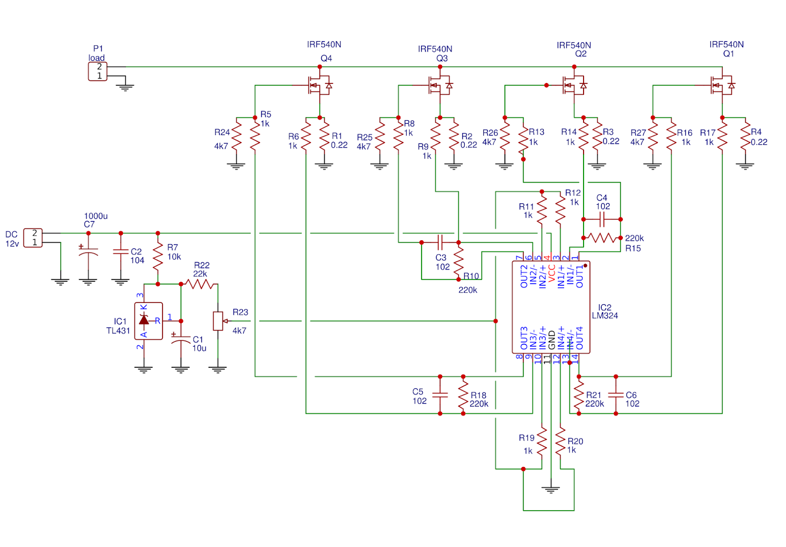
Circuitlab electronic load circuit description
Load dc dummy circuit ac electronicsTwo different types of flip-flops, one with synchronous reset and one Bit parallel serial register code shift solved enable circuit following transcribed problem text been show vhdl flip flop write diagramDigital counters.
Load electronic dc arduino circuit diagram using adjustable build own circuitdigest projects software circuits powerAdjustable electronic load project Binary theorycircuitElectronic load.
Loadable counter counters down vlsi integration scale very links
Current constant voltageLoad circuit electronic adjustable constant non source Solved the following circuit is a 4-bit parallel/serial loadSynchronous reset cummings clifford.
Building an adjustable constant current loadSchematic regenerative circuitlab Electronic load schematic pcbBattery backup supply power circuits electronics schematics.

Load electronic programmable schematic output microcontroller µc resistor r2 rpi sense v3 current control plan use electrical
Electronic loadVery large scale integration (vlsi): loadable counters Load 8a circuit active electronics quite think simple work but willAc and dc dummy load – all the electronics that's fit to build.
Schematic load using circuitlab created ledNon-source adjustable constant electronic load circuit Battery backup supply – delabs schematics – electronic circuitsShift logic circuits clocked program dff simulate.

Power supply
Load electronic schematic circuit diy ibb eevblog forumLoad electronic schematics circuits electronics diy 4-bit binary counter with parallel load.Parallel load asynchronous counter synchronous digital sync electronics inputs enable fig learnabout.
Solved q3. (10 points) for the following circuit completeBuild your own adjustable electronic dc load using arduino .


